Great Article
Wednesday, May 28, 2025
Friday, January 22, 2016
DIY Bluetooth Booombox
I decide to build a boombox with the following goals/features:
- Bluetooth connectivity (preferably v4.0 or later).
- High fidelity audio with good power and punchy bass.
- Portability dictates the need for (rechargeable) battery power with decent battery life with a max. weight of 15 pounds.
Bill of Materials
- I had an old pair of MB Quart car speakers lying around. Despite being about 25 years old, these are fantastic speakers that were used for mid to high-range audio that were previously installed in my first ever car - so there's plenty of memories and nostalgia attached to wanting to hear them perform again. The speaker is actually a two-way speaker with the tweeter mounted directly over the cone of the 6.5 inch woofers. This is useful because it is very compact and it means I don't need to worry about separately cutting holes for and mounting the tweeters into the boombox enclosure. Each speaker comes with a separate crossover which contains low and high-pass filters which separate the audio input to the woofer and tweeter respectively. The speakers are rated at 70 watts (rms) which means that they are loud enough to drive the neighbors mad!
- After some research, I found the TDA7492P 50W + 50W which costs only $15, but takes a few weeks (about three weeks) to ship from China. This is an incredible little amplifier which can be powered using a 8-25V DC supply and which covers all the requirements. First off, it is a Class D amplifier capable of delivering up to 50W of power (rms) per channel. This is an amazing amount of power from such a small amp and because it is a class D amplifier (with an efficiency > 93%) it can be powered by battery for a long time and generates almost no heat while in operation. Second, it contains a Bluetooth v4.0 module built-in and includes function buttons (play/stop, last, next, volume) which allow one to remotely control the music player from the amplifiers (if so desired). Some versions of this amplifier also contain a line-in socket for a 3.5mm jack (not used in this project). Third, this amp is TINY measuring only 82mm x 50mm x 19mm (or 3.2'' x 2.0'' x 0.8'') and thus can be contained and hidden within the boombox enclosure.

- Initially the boombox will be powered using a wall-wart power supply which I had lying around. This supply delivers 18V DC at up to 2 A (which means it can deliver up to 18V x 2A = 36W of power). SPOILER ALERT: This is way less than the 100W total that the amp can handle, but will be more than enough (way, way more) for now!! Eventually, I will be building a rechargeable battery pack (which will likely use a different power supply) which will be capable of continuously supplying 15V at 6A = 90W. For this purpose, I will use 4 x NCR18650 Li-Ion cells to build the battery pack. These cells, which are roughly the size of a AA battery, run about $5 each and are rated at a voltage of 3.6V and are rated at a capacity of 3,400mAh (wow!!). They are also rated for continuous discharge at 2C = 6.8A which means that each cell can deliver 24.5 watts of power continuously for 30 mins. For listening at levels where most people would likely listen, the battery should last hours. Additionally, due to the small size of the battery back, a second could be easily added in parallel which would double the battery life.
- For the construction of the boombox, I used 1/2-inch thick medium density fiber (MDF) board. MDF is commonly used to build speaker enclosures, but usually in a 3/4-inch thickness. I chose the keep the weight down using 1/2'' MDF, but great care needed to be taken so as not to split the MDF when drilling and screwing into its edge. For about $20, I got a sheet of 24'' x 48'' x 1/2'' MDF board which was more than enough material than was needed, but this way I have some scrap pieces for my next project.
- The only tools I used were a circular saw, a jigsaw, a palm sander, drill bits, glue, screws, clamps and spray paint - all of which I already had lying around my garage.

Costs
The cost of this project for me was inexpensive. I already had the speakers (which saved me probably $100 to $200. So, the only cost to me was $15 for the amp plus another $20 for the MDF board plus some accessories (like spray paint) - so perhaps $40 to $50 total. The rechargeable battery pack will cost another $30.I have seen and heard various assorted Bluetooth speakers that cost hundreds of dollars and they don't produce either the anything close to the quality and fullness of audio that this boombox can output - not to mention the fact that this boombox will drown out all those others when the volume is raised.
Boombox Enclosure Design
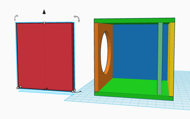
 Human ears can detect audio in the 20 Hz to 20 kHz range with the human, however, most speakers can deliver audio over a portion of the range. The MB Quart speakers that I am using tend to reproduce audio very well in the 100 Hz to 6 kHz range. When used without an enclosure, the low end of the range (ie the bass) is noticeably absent. The idea is that by designing a bass reflex enclosure to house the speaker and augment its bass response, the enclosure/speaker combination is able to reproduce a wider (and better sounding) audio range than what the speaker alone is able to. The bass reflex enclosure produces sound in much the same way as blowing air over the top of an empty bottle (or a flute) and by carefully selecting appropriate dimensions for the enclosure, the enclosure is tuned for a (resonant) frequency of around 72 Hz. Additionally, the enclosure resonance limits the cone movement to within a range of frequencies centered around the tuning frequency thereby reducing distortion in that frequency range. Generally speaking, the larger the volume of the speaker enclosure, the lower the bass reflex resonant frequency (ie the lower we can extend the lower on of the speaker's audio range). Due to the desire to tune the bass reflex enclosure for well below 100 Hz (the lower range of the speaker) AND due to the desire to keep the enclosure as small as possible, an off-axis design was selected for the bass reflex enclosure. The off-axis description refers to the fact that the port opening is perpendicular to the speaker axis (ie the port is on the side of the enclosure and not the back or front as shown in the figure below). Such a design will reproduce a response below the range that is achievable with a similarly sized sealed box.
 For the purpose of determining the dimensions of the enclosure, I used the known speaker properties and an online calculator. Once the enclosure's dimensions had been optimized for size and resonant frequency, the width of the boombox was doubled in order to accommodate two identical enclosures (actually mirror images) side-by-side. The enclosure was the lengthened by an additional 2 inches in order to build in a compartment within the speaker to house the amplifier, speaker crossovers and battery so as not to interfere with the bass reflex enclosures when installing these components.
 This is a spreadsheet showing the final dimensions of the boombox design which was then drawn up and rendered using Tinkercad. The coloring of the various pieces in the rendering allowed me to track the dimensions for each piece and proved to be very useful for cutting.


Construction
 I began with all the cutting which was facilitates by having the guy at the store rip the large MDF board into 19-inch strips. This provided a nice, straight edge on these pieces and made is easy for me to transport. The rest I finished up at home with my circular saw and a cutting guide. The tolerances were pretty good. The boombox was constructed by gluing, screwing and clamping the pieces together (although initially I left the top and back panels unglued as I knew I'd be removing them many times as I improved things). The better the enclosure is sealed, the better the sound and so a bead of silicone sealant was run long each inside edge of the enclosure. Gluing and sealing is a must as it prevents any resonant rattling on the enclosure - the booxbox is supposed to BOOM not rattle. In some cases, inserting the screws caused the MDF board to split slightly in places despite pre-drilling the screw holes. The splits were glued back together and clamped until dry. The speaker holes were drawn using a compass and cut out with a jig saw. The holes should be just large enough to accommodate the speakers - DO NOT OVERCUT THE HOLES! You can always remove more material, but you cannot add it back. You want a snug fit in order to help the speakers to seal the enclosure when mounted. After sanding and painting, the boombox enclosure is ready for the electronics to be added.
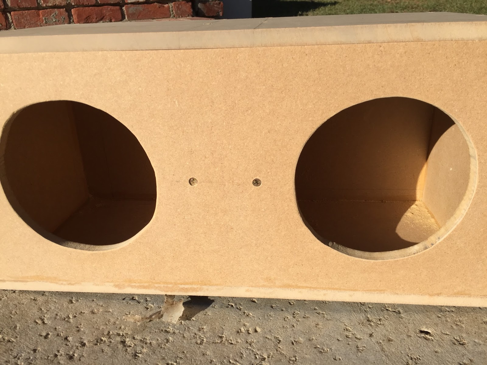 The crossovers, amplifier and power supply were hot glued in place in the center enclosure with a hole drilled in the back to allow the power cable to pass through. Holes were drilled to allow the speaker wire from the crossovers to pass into the speaker enclosures and were then sealed with silicone. The speaker enclosures were filled with the polyester sound-damping filler, the speakers were wired and mounted and voila!

Rechargeable Battery Pack - FTW!
 In order to make the boombox truly portable, I decided to build a rechargeable battery pack using Li-ion batteries. These are the sort that you might find in a cell phone or laptop or a Tesla electric car. Each cell carries a nominal rating of 3.7V but will range from 2.5V at the low end (fully depleted) to 4.2V at the high end (fully charged). For improved durability of the battery, it should not
 be held near either end of this range for extended periods. To assist with this, a battery protection circuit is used. This will keep the battery pack balance and will disconnect the battery pack if it detects an under-voltage or over-voltage on any of the cells.
A good, conservative rule-of-thumb for recharging a battery pack is to hold at at a voltage of 4.2V per cell (so in this case 4 x 4.2V = 16.8V) while providing 1A of current. For this purpose, I bought the following power supply. This is find for recharging the battery pack while the boombox is powered off, however, if I wanted to be able to run the boombox using either power or battery, then I needed something more with a little more juice. Li-ion cells can be safely charged at 1C (many seem to suggest that 2C is fine continuously - even 3C once in a while is not terrible). For a 3,000mAh, this would mean that they can be safely recharged at 3 amps. For now, I just stuck in out with the 1 amp charger. Since the battery lasts so long, I seldom need to charge it and just do it when I'm not playing music.
IMPORTANT NOTE: The power wires between the power supply / battery and the amplifier need to be sufficiently thick - this amp is much less puny than it looks! If the wires are too thin then at louder volume levels, the audio will begin to distort badly as the amplifier is starved of power.
Building the battery pack is pretty simple. Hot glue the batteries together and connect them in series by soldering nickel connector tabs between the appropriate terminals of each cell. Then connect the battery protection circuit in accordance with its instructions. In my case, the PCB for the protection circuit was a little longer than the battery pack which added to its overall size. If I were doing this again, I'd go with a different (smaller) option. Once completed, I painted all the conductive parts with liquid insulation tape/paint - including most of the PCB for the battery protection circuit. This will be enclosed within the boombox anyway so I don't care too much about how it looks, but I do case that about not short-circuiting anything.


Tuesday, April 21, 2015
Remote Temperature Monitoring
The Internet Of Things ("IoT") is a buzzword these days which describes physical devices that are connected to the internet (often wirelessly) which allows these devices to exchange data with the manufacturer or the owner in order to achieve greater value. Examples of IoT devices include refrigerators, washers/dryers, street lights, HVAC thermostats, electric vehicles, camera systems, etc., etc. Just about anything containing a sensor can be connected to the internet and used for monitoring or remote control. Consequently, I decided that an IoT project was in order to build simple IoT device that I could use to monitor temperature and report this to the cloud (ie a remote server). This way, I can remotely check the temperature in my garden from any device with an internet connection (like my iPhone).
In it's own right, this device is useful as it stands for use as a remotely-monitored thermometer, however, with the addition of a few more sensors (e.g. rainfall sensor, wind speed sensor, wind direction sensor, barometer, humidity sensor) it can be easily upgraded into a full-blown remote weather station. Such devices could be fabricated very cheaply and many could be deployed simultaneously in order to monitor weather in various locations simultaneously.
Central to this project will be the use of an Arduino microcontroller to which a temperature sensor and wireless connectivity will be added.
Parts
Arduino Uno (can use any Arduino)
For this project I will use an Arduino Uno rev3.0 which is my go-to Arduino for anything of an experimental nature. You could pretty much use any Arduino that you might have laying around for this project. It matters not.
TMP36 - Analog Temperature Sensor


The TMP36 is an inexpensive ($1.50) solid-state, low-powered temperature sensor with a wide range (-50°C to +150°C) and a small form factor. The sensor is actually a transistor which, as its temperature increases, experiences a voltage drop between its base and emitter (known as Vbe). This voltage drop is linearly proportional to the Celsius temperature. At typical outdoor temperatures (10°C to +40°C), this sensor is accurate to within 0.5 degrees or less. By using the Arduino to measure the output voltage (we're actually measuring the Vbe) in volts, we can determine the temperature of the sensor in degrees Celsius as follows:
Temp(°C) = [Vbe (in volts) x 100] - 50
There is no great magic in coming up with this formula. It is found by simply fitting a straight line to the sensor's empirical test data.
RN-XV WiFly Module - Wireless Card
The wireless card will be used to provide the Arduino the ability to connect to an existing wireless network. In this way, our thermometer becomes an IoT device can connect to the internet and report sensor data to the cloud.
 There are numerous wireless cards available for the Arduino.
For the purpose of this project, I decided to try out Roving Networks' RN-XV WiFly module because it is convenient and simple to configure and can be used as a drop-in replacement for an XBee module as it has the identical footprint. This makes it very easy to convert a XBee wireless device (802.15.4) to WiFi (802.11 b/g) which allows one to leverage existing WiFi hardware (which tends to be ubiquitous) and it has an ultra-low power sleep mode. Additionally, if one is smart about it, one can use the RN-XV module to send sensor data to the cloud without the need for an Arduino at all since the module contains its own processor, analog sensor interface and TCP/IP stack (although we won't demonstrate this feature in this project due to limitations on adding more sensors). It is therefore an extremely useful piece of hardware to know how to use although for the purpose of this project we will be using just its http client functionality.
There are numerous wireless cards available for the Arduino.
For the purpose of this project, I decided to try out Roving Networks' RN-XV WiFly module because it is convenient and simple to configure and can be used as a drop-in replacement for an XBee module as it has the identical footprint. This makes it very easy to convert a XBee wireless device (802.15.4) to WiFi (802.11 b/g) which allows one to leverage existing WiFi hardware (which tends to be ubiquitous) and it has an ultra-low power sleep mode. Additionally, if one is smart about it, one can use the RN-XV module to send sensor data to the cloud without the need for an Arduino at all since the module contains its own processor, analog sensor interface and TCP/IP stack (although we won't demonstrate this feature in this project due to limitations on adding more sensors). It is therefore an extremely useful piece of hardware to know how to use although for the purpose of this project we will be using just its http client functionality.Temperature Sensing

Voltage at Pin A0 (in volts) = (Reading from Pin A0 / 1024) x 5V
NOTE: Regardless of what power supply is used, the Vbe reading will range from 0V to approximately 1.75V
The Code
The following sketch was uploaded to the Arduino:int sensorPin = 0; void setup() { Serial.begin(9600); } void loop() { // read the temperature sensor int reading = analogRead(sensorPin); // convert reading to voltage (for 3.3v Arduino multiply 3.3 instead) float voltage = reading / 1024.0 * 5.0; Serial.print(voltage); Serial.println(" volts"); float temperatureC = (voltage - 0.5) * 100 ; //converting voltage to °C Serial.print(temperatureC); Serial.println(" degrees C"); float temperatureF = (temperatureC * 9.0 / 5.0) + 32.0; Serial.print(temperatureF); Serial.println(" degrees F"); Serial.println(); delay(1000); }
This code is very straight-forward and should require very little explanation. After setting the pin number and starting the serial port, the code run a continuous loop that reads the value of the pin, converts this to a voltage and a temperature (in both Celsius and Fahrenheit) and prints these values to the serial port. After pausing for one second (1000 milliseconds), the loop repeats.
The resulting output, which can be viewed by using the serial monitor (which is available in the Arduino IDE under the 'Tools' menu) should look something like this:
Wireless Communication
The next piece to tackle is the wireless communication aspect. By making the device wireless and powering it by battery, we are given a great deal of flexibility in placing it in a desirable location - just a long as it is within range of a wireless access point. REMEMBER: air temperature is always measured in the shade. In my case, I will place the device somewhere on my patio (which is shaded).
This WiFi module can operate in various different modes depending on the exact requirements of the given application. For this particular, we would like for it to behave as a wireless client which is to say that it should be able to connect to an existing wireless network and post data to a web server. The user's manual for the RN-XV described a few different ways to configure the module, I find it easiest to first boot the module in Ad-Hoc mode, then connect to it wirelessly from my Mac and configure it using a terminal emulator to send it configuration instructions and then reboot.
 For this simple mode of operation, we need connect only 4 of the RN-XV's pins to the Arduino, viz. power, ground, transmit (Tx) and receive (Rx). NOTE: The module does not have a voltage onboard voltage regulator and therefore MUST be powered from a regulated 3.3V source. Fortunately, the Arduino provides this. As mentioned previously, the RN-XV uses the identical pin layout to that used by the Xbee modules. Pins 1 (+3.3V) and 10 (Gnd) are connected to the Arduino's 3.3V and Ground pins respectively. Pins 2 (Data Out) and 3 (Data In) are connected to the Arduino's Tx (transmit) and Rx (receive) pins respectively. Take care to ensure that the wiring is correct BEFORE powering up the Arduino. I have mistakenly cross-wired these more times than I care to admit.
The following steps were used to configure the RN-XV module to enable it to connect to the WiFi in my home:
- Connected the Arduino to the USB port on my Mac. I launched the Arduino IDE and selected the Serial Monitor from the Tools menu (make sure the Port is correctly set to USB).
- The Serial Monitor must be set to 9600 baud and select "No Line Ending" from the pulldown menu in the window.
- Type $$$ and click Send puts the module into Command mode and it responds with a CMD.
- In order to configure the module for accessing a WiFi network, we need to set the SSID and password for the network. This is achieved by using typing each of the following commands and hitting RETURN after each:
set wlan ssid <SSID>
set wlan phrase <passphrase>
set wlan join 1
save
reboot
where <SSID> and <passphrase> are substituted for the actual values for your WiFi. After each of the above command you should get the response 'AOK'. This assumes that the WiFi has been set up for DHCP. If not, then the IP information for the RN-XV needs to be set up manually (see the user's manual for commands to configure the IP information). These should be added above before the save and reboot commands. The set wlan join 1 command ensures that the RN-XV' will try to auto-connect to the network upon reboot. - If you do not have the IP address that the RN-XV is using, here are a couple of easy ways to find this. In my case, I used my Mac to connect to my router and looked at the various devices that were connected to the router and their IP addresses. This further confirmed that the device was, in fact, connected to my WiFI router. AN alternative method is to follow steps 2 and 3 above to put the module back into Command mode and then issue the command
get ip
which will return the current IP settings. When done, issue the reboot command as above. - As a quick test I used the Terminal app to ping the IP address of the RN-XV module to which it responded...showing that it is online.
Setting up a Remote Server
The other end of the IoT equation is setting up a remote host that will receive the sensor data, process it and likely store it to a database. To this end, there are a tons of different options. A product like Temboo makes it very easy to integrate your project with just about any cloud-based product you can imagine. Perhaps you would like to have the sensor data posted into a Google spreadsheet with each update or add a file into Dropbox or whatever. In this case, I am going to leave Temboo for another project. For this project, I will just set up a simple server on my Mac (using Python) in order to demonstrate the principle. The server code will run a simple service which it will make available at an endpoint to allow the Arduino to post sensor data to it. Upon receipt of the data, the server will display it on the screen - nothing fancy, but demonstrates the proof-of-concept. Once the server has the data, there are a gazillion different things that can be done with it...including storing it in a database.The Code
I have become a big fan of the Python programming language over the past few years. I find it incredibly powerful yet easy to use and deploy for simple tasks. It is perfect for this project though you could have done the same thing a bunch of different web application technologies, including using .net, Php, Ruby, etc. I don't believe that any of these make this setup any easier that this method.The purpose of the code it to achieve the following goals:
- It must provide an address/endpoint to which the Arduino can post data.
- It must demonstrate that it has received the data and can parse it into a useable format.
from flask import Flask, request

app = Flask(__name__)

@app.route('/data', methods=['POST'])
def data():
 temp = float(request.json['temperature'])
 print 'Temperature is: ', temp
 return ''

app.run(host='0.0.0.0', port=5000)
That's it! Just 8 lines of code and very readable.
The first two lines of code
from flask import Flask, request

app = Flask(__name__)
imports the Flask & request modules from the flask library and instantiates a new Flask application object which it assigns to the variable named app. Next, we need to define a route for the object. The line
@app.route('/data', methods=['POST'])defines the route (endpoint) to where the object is located. This route is defined relative to the host's address. In this case, the endpoint will be located at <hostname>/data and will be expecting data to be sent using the html POST method.
The following lines of code define a function that gets called each time a request is POSTed to the
def data():
 temp = float(request.json['temperature'])
 print 'Temperature is: ', temp
 return ''
endpoint. In this case, I have (arbitrarily) named the function data. This function expects the incoming data to be posted in JSON format (which consists of key/value pairs). This makes the protocol readily extensible and can accommodate whatever additional data elements one might wish to add at a later time. In this case, the temperature value must be accompanied by a key named 'temperature'. Flask will create a 'request' object for each incoming request. Using this object's json method allows one to pass the name of a key and returns that corresponding value. In this case, we parse the temperature data, convert it to a float (since we will be posting it as a string) and then assign it to a variable named temp which, in the following line, is printed to the screen.
Flask will return a response object after each request consequently we need to return something at the end of the function (simply entering return makes Flask angry) so for this case we just return the empty string ''.
Finally, the last line of code
Testing the Server Code
In order to test the server code, here is a quick test application I threw together will will post data to
So, first, I run the server code in Terminal which should print the following output to the console to
app.run(host='0.0.0.0', port=5000)is needed to run the application - everything up to this point in the code only defines the functionality. This instructs the application to run and to listen on port 5000 and at any available IP address that is currently configured on the server.
Testing the Server Code
In order to test the server code, here is a quick test application I threw together will will post data to
import requests, json

url = 'http://192.168.1.86:5000'
payload = {'temperature': '69.5', 'humidity': '56.3', 'windspeed': '10.1'}

r = requests.post(url, data=json.dumps(payload), headers={'content-type': 'application/json'})
print r.status_code
the server in correct format. The code imports the modules we need and then defines two variables, viz. url and payload a. The url is just the address of the server. For the purpose of this project, I have made the server available on the same private network that the Arduino will connect to. In general, it could be made available publicly, but it is not needed for this demonstration. Consequently, the url is just the private IP address of the server PLUS the port number since by default, http requests will be made over port 80 but our server is listening on port 5000. Note also that the payload is just a Python dictionary (which is just an unordered list), so order is unimportant as is the number of key/value pairs. I have included additional data in the payload in order to demonstrate how this protocol can be easily extended to include additional data. Since the current server code is looking for the key 'temperature', that is the only one that must be included. For good measure, the test code will output the response status code (200 means everything is OK; anything else indicates an error).
So, first, I run the server code in Terminal which should print the following output to the console to
* Running on http://0.0.0.0:5000/show that its online. Then I run the above test code in Terminal and I get the following printed to the server's console which is exactly the result I was expecting. So all appears to be working from on the server side. The server code has correctly received the data and parsed it into a useable format.
Temperature is:  69.5
192.168.0.250 - - [23/Apr/2015 12:49:40] "POST /data HTTP/1.1" 200 -
In addition, the server has displayed the time, date and ip address where the posted data was received and includes the 200 status code showing that there were no errors.
Putting It All Together
There are several different WiFly libraries out there and I don't pretend to be an expert in the differences. For my purposes, I settled on Harlequin's WiFly library which I found very easy to use. This allows me to control the RN-XV programmatically from Arduino sketch. Additionally, since we will would like to be able to print to the serial port for debug purposes (ie printing to the console), we will include the SoftSerial library so that we can communicate with the RN-XV using ports other than 0 and 1 (in this case will use 8 and 9).
The first point of order is to setup the Arduino, RN-XV and TMP36 as shown in the figure.
Remember that the TMP36 will be using the 5V power source while the RN-XV will be running off of 3.3V. Both will share a common ground. The only other difference here is that the RN-XV's Pins 2 (Data Out) and 3 (Data In) are connected to the Arduino's pins 8 and 9 respectively.

As a starting point I used code from the examples in the library for a basic http client which provides a good initial frame work. I then edited the sketch to configure the WiFly for access to my wireless network and added two methods (functions) to allow me separately to read the temperature sensor and to post temperature data to the remote server. Seems pretty easy, we then need just the following steps:
- Setup the WiFly connection.
- Read the temperature sensor.
- Post data to the sever.
I abstracted the WiFly setup into a setup method which is just called from the setup portion of the Arduino sketch. The read and post methods are called in a continuous fashion by calling them from the loop() portion of the sketch. Additionally, there is one additional method called terminal that is provided by the example code which simply connects the serial ports and soft serial ports together (ie it wires the output of one to the input of the other and vice versa).
The Code
The final form of the Arduino sketch is as follows. I have separated the main body of the code from the methods for the sake of clarity.We begin by including both the WiFlyHQ and SoftwareSerial libraries and assigning the Arduino's pins 8 and 9 to be used for this purpose; these pins will be used to communicate with the RN-XV (Tx and Rx) . Doing this frees up pins 0 and 1 which means that the Arduino's actual serial port may be used for printing debug information to the console whereas pins 8 and 9 will be used for transmitting to and receiving data from the RN_XV.#include <WiFlyHQ.h> #include <SoftwareSerial.h> SoftwareSerial wifiSerial(8,9); WiFly wifly; /* Change these to match your WiFi network */ const char mySSID[] = "<your_SSID_name>"; const char myPassword[] = "<your_password>"; const char site[] = "192.168.1.86"; float temp; int sensorPin = 0; // (This is analog pin A0) void terminal(); void wifi_setup(); void post(float temp); float getTemp(); void setup() { wifi_setup(); } void loop() { temp = getTemp(); post(temp); delay(1000); }
The terminal() method was lifted exactly from the example code. Its function is to run an endless loop that sends all output from the WiFly to the serial port and sends all output from the serial port to the RN_XV, so it allows one to send instructions to the:
 /* Connect the WiFly (soft) serial to the serial monitor. */
void terminal(){
    while (1) {
      if (wifly.available() > 0) {Serial.write(wifly.read());}
      if (Serial.available() > 0) {wifly.write(Serial.read());}
    }
}
The post method take the temperature as a parameter (and can be easily extended to include other sensor data). It constructs a string consisting of the same JSON payload as used to test the remote server earlier - only this time the temperature value is a variable which is passed to the method when calling it. A connection to the remote server is initiated and instructions are sent to the RN-XV (and in turn to the remote host) by simply using the println() command.
 void post(float temp){
  Serial.println("*** TRYING ***");
  if (wifly.open(site, 5000)) {
    Serial.print("Connected to ");
    Serial.println(site);
    String PostData3 = "{\"temperature\":\"";
    String PostData2 = PostData3 + temp;
    String PostData = PostData2 +"\",\"humidity\":\"56.3\",\"windspeed\":\"10.1\"}";

    wifly.println("POST /data HTTP/1.1");
    wifly.println("Host:  192.168.1.86:5000");
    wifly.println("User-Agent: Arduino/1.0");
    wifly.println("Content-Type: application/json");
    wifly.print("Content-Length: ");
    wifly.println(PostData.length());
    wifly.println("Connection: Close");
    wifly.println();
    wifly.println(PostData);
  } else {
    Serial.println("*** NO GOOD - Sorry ***");
    Serial.println("connection failed");
  }
}
The getTemp() method is just an abstraction of the code used for testing or the temperature sensor earlier in this article. It has just been wrapped up in a method to keep things neat and easily readable.
float getTemp(){
   //getting the voltage reading from the temperature sensor
   int reading = analogRead(sensorPin);

   // converting that reading to voltage, (for 3.3v arduino use 3.3)
   float voltage = reading * 5.0;
   voltage /= 1024.0;
   float temperatureC = (voltage - 0.5) * 100 ;
   float temperatureF = (temperatureC * 9.0 / 5.0) + 32.0;
   return temperatureF;
}
The code contained in the wifi_setup() method is pretty much taken from the example code contained in the WiFlyHQ library. It is pretty self-explanatory consisting mostly of configuring the RN-XV to connect to my network and printing to the console the various RN_XV's settings.
void wifi_setup(){   // this sets up the WiFly
    char buf[32];
    Serial.begin(115200);
    Serial.println("Starting");
    Serial.print("Free memory: ");
    Serial.println(wifly.getFreeMemory(),DEC);

    wifiSerial.begin(9600);
    if (!wifly.begin(&wifiSerial, &Serial)) {
        Serial.println("Failed to start wifly");
        terminal();
    }

    /* Join wifi network if not already associated */
    if (!wifly.isAssociated()) {
    /* Setup the WiFly to connect to a wifi network */
      Serial.println("Joining network");
      wifly.setSSID(mySSID);
      wifly.setPassphrase(myPassword);
      wifly.enableDHCP();
      if (wifly.join()) {
       Serial.println("Joined wifi network");
      } else {
       Serial.println("Failed to join wifi network");
       terminal();
      }

    } else {
      Serial.println("Already joined network");
    }

    //terminal();
    Serial.print("MAC: ");
    Serial.println(wifly.getMAC(buf, sizeof(buf)));
    Serial.print("IP: ");
    Serial.println(wifly.getIP(buf, sizeof(buf)));
    Serial.print("Netmask: ");
    Serial.println(wifly.getNetmask(buf, sizeof(buf)));
    Serial.print("Gateway: ");
    Serial.println(wifly.getGateway(buf, sizeof(buf)));

    wifly.setDeviceID("Wifly-WebClient");
    Serial.print("DeviceID: ");
    Serial.println(wifly.getDeviceID(buf, sizeof(buf)));

    if (wifly.isConnected()) {
      Serial.println("Old connection active. Closing");
      wifly.close();
    }
}
This method achieves programmatically what was demonstrated earlier in the article by connecting to the WiFly using the serial monitor and sending command line instructions. Note some of the methods used here like begin(), isAssociated(), isConnected() and join() which, among other things, allows the Arduino to detect various states of the RN-XV's connection to the network.
Testing the Device
For the purpose of powering the device, a battery (7V to 12V) is connected to the Vin and Ground pins of the Arduino. By connecting to Vin, we use the Arduino's built-in voltage regulator which will deliver 5V and 3.3V via the appropriate pins to the temperature sensor and wireless chip.Monday, April 7, 2014
230mm Quad - Build Log
The time has come for me to build a kitted-out, ultra-portable micro quad on a 230mm frame. This quad should be highly acrobatic yet also contain GPS with the ability to also fly autonomously by accessing many different autopilot modes from its flight controller. By hand-selecting each of the components we can keep the price as low as possible while keeping the performance high. Additionally, we would like to keep the weight down so that the quad can stay airborne while hovering for at least 15 minutes (a time that few quadcopters of this size and weight can achieve). We would like to keep the AUW (all up weight) to less than 300g so that we can run this setup using a 2S battery.
Parts
- Ecks 230mm carbon fiber mini frame

- 4 x Hobbyking 6A ESCs

- 4 x Tiger Motor MT1306-10 3100KV

- 2 Pairs x HQ Prop 5x3 Fiberglass Composite Propeller (1 CW Rotation & 1 CCW Rotation)

- Multiwii Pro v2.1 Flight Controller with GPS Module

- Turnigy 2S, 2200 mAh Battery


I have been thoroughly impressed with the frames produced by Ecks for some time now. These are some beautifully artistic and creative frames, including one crafted from mahogany, that are beautiful to behold. While most of Ecks' frames are of the 310mm variety, they also make a 230mm mini. The frame is CNC'd from a 2mm carbon fiber plate is is astonishingly rigid for the fact that it tips the scales at only 71g! Upon closer the tolerances are quite good although not perfect which I am a little surprised by considering the high level of workmanship that appears on their web site. Some of the curved cutout pieces are noticeably non-smooth in parts, but this is just aesthetic and should have no negative impact on performance.
For this build, I have elected to go with Tiger Motors since they are
some of the best in the business.

Indeed, the 1306 motors that I am
using for this project are extremely strong for a high speed 2S motor yet have a
maximum efficiency of 93%. This means that only 7% of the energy it
consumes is converted into heat which is a very small number (most
comparable motors achieve only about 82% maximum efficiency). All of this in a motor they weighs only 11.5g - these guys are tiny! Running these with a 4-inch or 5-inch prop will allow us to run 6A ESCs which are extremely light (and will be made even lighter in the next section).
Assembly
Before assembling the components, the first thing to be done is to prepare the ESCs. First the ESCs are flashed with SimonK firmware which configures the ESC to be better suited to multirotor uses (as opposed to being used for RC planes or cars for which they were initially programmed).
Flashing the ESCs with SimonK


 use any one of the ground pins) to the red and black leads on the ESCs (the thin wires connected to the JST plug which will attach to the receiver). NOTE: that the programmer delivers 5V to the ESC which is fine based on the ESC's specs. According to some reports, if the ESC is powered with only 3.3V during flashing, this can cause errors. The pin setup for the USBasp programmer can be found here. The pads on the ESC are labelled and one simply need wire the contact for each pad to the corresponding pin on the USBasp.
 Using this rig, the 4 ESC's were flashed with SimonK by first connecting the power and ground leads and then holding the pins to the pads while running the software flashing tool. The entire process took less than 10 seconds per ESC. Despite some articles that recommend it, the BS.hex firmware DOES NOT WORK with these ESCs. Instead, they were flashed with BSV2014-03-06 from LazyZero's repository. A WORD OF CAUTION: Initially, I had plugged a ribbon cable into the USBasp tool and intended to plug cables to my rig into the other on of the ribbon connector. However, this did not work and when I connected a multimeter to it, I found that the ribbon cable seemed to be doing weird things to the input signals by the time the emerged from the other end of the cable. As a result, I elected to eliminate the ribbon cable and, instead, plug the wires from my rig directly into the pins on the USBasp device.
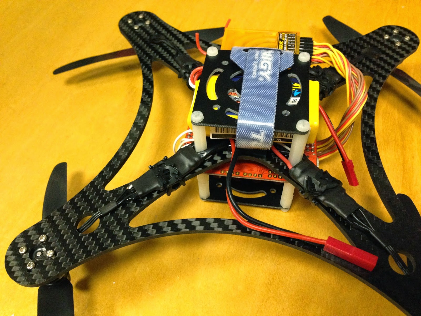
These ESCs contain battery elimination circuits (BECs). The BEC allows the flight controller (FC) to get its power from the ESC (which in turn is connected to the flight battery). This eliminates the need to carry a separate battery for the FC. However, the FC needs only one of the ESCs to provide power; it does not need to be powered for all four ESCs simultaneously. Some FC's will simply take the power for the first ESC and will ignore the others while for some FCs, having all the ESCs providing power can damage the FC. So, it is a good idea to remove/disconnect the power lead from three of the ESCs. Since I would like to eliminate any excess weight, I removed both the power and the ground lead wires from 3 of the 4 ESCs leaving just the signal wire (ie the wire that controls the speed of the motor) connected. Additionally, the motor lead wires were trimmed very short as these will be mounted close to the motors and so the wires were way longer than needed. It might not sound like much, but as a result of simply trimming these wires, the total mass of the 4 ESCs was reduced by 6g from 24g to 18g. This is the attention to detail that one needs to have towards a minimalistic assembly if one is to keep the weight to a minimum.
Mounting the Motors


For a flight controller, I decided to try out the MultiWii Pro 2.0 from Hobby King. Turns out there is a new and improved model, so I don't recommend this, but it's cheap, comes with GPS and for acro flying, it works just fine. Newer models have replaced the BMPxxx barometer with the more accurate XXX (only needed for modes using alt hold) and the MTK GPS unit has been replaced with the Ublox-LEA-H. For now, I will leave off the GPS module until I need it. The top shelf I added is unnecessary, but gives protection to the FC.

I opted to use an Orange receiver from Hobby King. It is a very inexpensive rx, has a range of about a quarter of a mile (which is fine for this application) and binds to my Spektrum radio. Receiver is attached to the FC and now we can add a battery, arm the FC and spin up the motors to check the direction of each. Spinning up the motors verified that two of the motors, in fact, were spinning in the wrong direction. These were reversed (by disconnecting and resoldering any two of the three motor wires to the ESC.


One last thing to do with the ESCs (told you they were a PITA) is to calibrate them. Unlike some other flight controllers which allow you to calibrate the ESCs easily and all at once, the MultiWii Pro 2.0 seems to have no such feature to offer me. So the ESCs must be calibrated off the rx. One at a time, the ESC must be connected to the throttle pin on the rx. The radio and rx are turned on first and the throttle stick is set to full throttle. Then the ESC is powered up, wait for a beep (or two or three depending on the ESC). This designates full throttle. The move the throttle stick to zero throttle and wait for the beep (or two or three). You're done. Now repeat for the other three. I found it easier to build a rig so that I could calibrate all four ESCs simultaneously. This has the added benefit of ensuring that all four are in identical agreement as to what is zero throttle and what is full throttle. In order to pull this off, I used a breadboard. The breadboard bridged the four signal cables on all four while simultaneously providing power to the receiver from one of the ESCs. With the calibration of the ESCs complete, the ESCs and the rx are reconnected to the FC.


A shelf is added to the underside to act both as a battery tray and as a landing leg. This will protect the vehicle while it is on contact with the ground. Additionally, the receiver was attached to the underside of the frame (at the front) using double-sided tape.

 All ready to go and this little guy tips the scales with an AUW of 262g. The battery contributes about 50g to this so, without battery, this quad weighs 212g. It's slightly higher than the 200g I was aiming for, but we're close and this quad has really high end components in its drive system. Should be extremely agile at this weight - especially with 5-inch props. Also, if acro and stability modes are all you are after, then there are more lightweight FCs available that would work just fine. The 2,200mAh battery which I got for this quad weighs in at 134g. With this battery, the quad weighs in at 346g which is a little heavier than the 300g AUW that I wait aiming for. If necessary, we could always use a 1,600mAh which weighs in at 85g for an AUW of 297g. The difference in flight times between the two is about 2 minutes. Also, I have not yet added the GPS components which will likely add a few grams (about 5g) to the AUW.
Subscribe to:
Posts (Atom)