Monday, April 7, 2014

230mm Quad - Build Log

The time has come for me to build a kitted-out, ultra-portable micro quad on a 230mm frame.  This quad should be highly acrobatic yet also contain GPS with the ability to also fly autonomously by accessing many different autopilot modes from its flight controller.  By hand-selecting each of the components we can keep the price as low as possible while keeping the performance high.  Additionally, we would like to keep the weight down so that the quad can stay airborne while hovering for at least 15 minutes (a time that few quadcopters of this size and weight can achieve).  We would like to keep the AUW (all up weight) to less than 300g so that we can run this setup using a 2S battery.

Parts

  1. Ecks 230mm carbon fiber mini frame
  2. 4 x  Hobbyking 6A ESCs
  3. 4 x  Tiger Motor MT1306-10 3100KV
  4. 2 Pairs x HQ Prop 5x3 Fiberglass Composite Propeller (1 CW Rotation & 1 CCW Rotation)
  5. Multiwii Pro v2.1 Flight Controller with GPS Module
  6. Turnigy 2S, 2200 mAh Battery
I have been thoroughly impressed with the frames produced by Ecks for some time now.  These are some beautifully artistic and creative frames, including one crafted from mahogany, that are beautiful to behold.  While most of Ecks' frames are of the 310mm variety, they also make a 230mm mini.  The frame is CNC'd from a 2mm carbon fiber plate is is astonishingly rigid for the fact that it tips the scales at only 71g!  Upon closer the tolerances are quite good although not perfect which I am a little surprised by considering the high level of workmanship that appears on their web site.  Some of the curved cutout pieces are noticeably non-smooth in parts, but this is just aesthetic and should have no negative impact on performance.

For this build, I have elected to go with Tiger Motors since they are some of the best in the business. 
Indeed, the 1306 motors that I am using for this project are extremely strong for a high speed 2S motor yet have a maximum efficiency of 93%.  This means that only 7% of the energy it consumes is converted into heat which is a very small number (most comparable motors achieve only about 82% maximum efficiency).  All of this in a motor they weighs only 11.5g - these guys are tiny!  Running these with a 4-inch or 5-inch prop will allow us to run 6A ESCs which are extremely light (and will be made even lighter in the next section).

Assembly


Before assembling the components, the first thing to be done is to prepare the ESCs.  First the ESCs are flashed with SimonK firmware which configures the ESC to be better suited to multirotor uses (as opposed to being used for RC planes or cars for which they were initially programmed).

Flashing the ESCs with SimonK


Following the procedure described in a previous article, I flashed the 6A ESCs.  Owing to their tiny size, this process was a pain to get right.  After removing the shrink wrap from the ESC, it is clear that the socket flashing tool cannot be used for the 6A as the form factor of the ATMEL chip is way smaller than that for the larger 12A and 16A ESCs and larger.  There are four copper pads provided on the PCB to allow one to connect the programmer.  Additionally, one needs to connect power and ground to the chip while flashing.  Rather than soldering lead wires to the 4 pads (which requires a very steady hand), I elected to build my own flashing tool, similar to what I used to flash my larger ESCs.  That would eliminate the need to tediously solder leads to each ESC and would thus provide a very quick and efficient way to flash the small 6A ESC.

I raided my Arduino parts drawer and decided to use 4 pins that I typically use to connect electronic components to the headers on an Arduino board.  I bent the pins slightly so that the tips of the pins aligned exactly with the pad on the ESC.  Next, I connected leads to the 4 pins and connected the other ends of the leads directly to my USBasp programmer according to the pin configuration described in this article.  Additionally, two more leads need to be added to provide power to the ESC.  For this purpose, I connected the Vcc and Ground pins from the programmer (you can
use any one of the ground pins) to the red and black leads on the ESCs (the thin wires connected to the JST plug which will attach to the receiver).  NOTE:  that the programmer delivers 5V to the ESC which is fine based on the ESC's specs.  According to some reports, if the ESC is powered with only 3.3V during flashing, this can cause errors.  The pin setup for the USBasp programmer can be found here.  The pads on the ESC are labelled and one simply need wire the contact for each pad to the corresponding pin on the USBasp.

Using this rig, the 4 ESC's were flashed with SimonK by first connecting the power and ground leads and then holding the pins to the pads while running the software flashing tool.  The entire process took less than 10 seconds per ESC.  Despite some articles that recommend it, the BS.hex firmware DOES NOT WORK with these ESCs.  Instead, they were flashed with BSV2014-03-06 from LazyZero's repository.  A WORD OF CAUTION:  Initially, I had plugged a ribbon cable into the USBasp tool and intended to plug cables to my rig into the other on of the ribbon connector.  However, this did not work and when I connected a multimeter to it, I found that the ribbon cable seemed to be doing weird things to the input signals by the time the emerged from the other end of the cable.  As a result, I elected to eliminate the ribbon cable and, instead, plug the wires from my rig directly into the pins on the USBasp device.

These ESCs contain battery elimination circuits (BECs).  The BEC allows the flight controller (FC) to get its power from the ESC (which in turn is connected to the flight battery).  This eliminates the need to carry a separate battery for the FC.  However, the FC needs only one of the ESCs to provide power; it does not need to be powered for all four ESCs simultaneously.  Some FC's will simply take the power for the first ESC and will ignore the others while for some FCs, having all the ESCs providing power can damage the FC.  So, it is a good idea to remove/disconnect the power lead from three of the ESCs.  Since I would like to eliminate any excess weight, I removed both the power and the ground lead wires from 3 of the 4 ESCs leaving just the signal wire (ie the wire that controls the speed of the motor) connected.  Additionally, the motor lead wires were trimmed very short as these will be mounted close to the motors and so the wires were way longer than needed.  It might not sound like much, but as a result of simply trimming these wires, the total mass of the 4 ESCs was reduced by 6g from 24g to 18g.  This is the attention to detail that one needs to have towards a minimalistic assembly if one is to keep the weight to a minimum. 


Mounting the Motors


The assembly begins with mocking up the motor/ESC assembly.  This allows one to determine the best way of routing the cables coming from both while trimming the cables to the correct length in order to achieve this.  I used a couple of small pieces of shrink wrap tubing per motor to keep the wires neatly together before attaching the motors to the arms using the screws accompanied the motors.  The wires were run down through the holes and to the underside of the frame where they'll be attached to the ESCs.

I cut the ESCs motor wires very short (usually, I would have removed the wires completely and soldered the wires directly to the ESCs, but these tiny ESCs are a pain to deal with, so I left a short piece of each wire attached to the ESCs to which to attach the motor wires).  The ESCs contain battery elimination circuits (BECs) that supply power from the main flight battery to the FC.  Only one ESC need supply power, so three of the four ESCs had the power and ground wires removed from the cable (and plug) that connects to the FC (the photo shows one of each ESC).

The ESCs were then bound to the underside of each arm using rapstrap (a cable tie will work too).  By positioning the ESCs on the quad's arms, the motor wires and corresponding ESC wires could all be trimmed to the correct length.

The next step is to connect the power wires for the 4 ESCs together and separately connect the 4 ground wires together.  For a larger quad build, I would typically elect to use a power distribution board for an easy hookup, but in the interest of saving both weight and space, I opted to solder the4 wire directly together.  I did, however, stagger the connections so I didn't end up with one giant solder joint and a bundle of wires.  This allowed the electrical system to be placed out of sight on the underside of the quad where it is protected by the undercarriage.

The connections are soldered directly instead of using connectors which add weight.  The only problem is that we do not know if the motors are spinning in the correct direction.  The chances are that two of them are not, so we cannot yet re-wrap the ESC with shrink wrap because we might still need to switch two of the motor wires in order to reverse the direction the motor spins.  So, the shrink wrap is cut and placed in position over the ESCs but is not yet shrunk and the motor wires are soldered to the ESCs. 

Attached a battery connector (make sure it contains a male plug) and the electrical on the underside is complete.  I will tape the power wires to the frame later using black insulation tape after I know that the motors are wires to the ESCs correctly.  This will hide the wires well.

The signal wires are routed through the center hole and to the top side of the frame where they will be attached to the flight controller.  From the top side everything looks super clean.  I am loving the look of this!

For a flight controller, I decided to try out the MultiWii Pro 2.0 from Hobby King.  Turns out there is a new and improved model, so I don't recommend this, but it's cheap, comes with GPS and for acro flying, it works just fine.  Newer models have replaced the BMPxxx barometer with the more accurate XXX (only needed for modes using alt hold) and the MTK GPS unit has been replaced with the Ublox-LEA-H.  For now, I will leave off the GPS module until I need it.  The top shelf I added is unnecessary, but gives protection to the FC.


I opted to use an Orange receiver from Hobby King.  It is a very inexpensive rx, has a range of about a quarter of a mile (which is fine for this application) and binds to my Spektrum radio.  Receiver is attached to the FC and now we can add a battery, arm the FC and spin up the motors to check the direction of each.  Spinning up the motors verified that two of the motors, in fact, were spinning in the wrong direction.  These were reversed (by disconnecting and resoldering any two of the three motor wires to the ESC.


One last thing to do with the ESCs (told you they were a PITA) is to calibrate them.  Unlike some other flight controllers which allow you to calibrate the ESCs easily and all at once, the MultiWii Pro 2.0 seems to have no such feature to offer me.  So the ESCs must be calibrated off the rx.  One at a time, the ESC must be connected to the throttle pin on the rx.  The radio and rx are turned on first and the throttle stick is set to full throttle.  Then the ESC is powered up, wait for a beep (or two or three depending on the ESC).  This designates full throttle.  The move the throttle stick to zero throttle and wait for the beep (or two or three).  You're done.  Now repeat for the other three.  I found it easier to build a rig so that I could calibrate all four ESCs simultaneously.  This has the added benefit of ensuring that all four are in identical agreement as to what is zero throttle and what is full throttle.  In order to pull this off, I used a breadboard.  The breadboard bridged the four signal cables on all four while simultaneously providing power to the receiver from one of the ESCs.  With the calibration of the ESCs complete, the ESCs and the rx are reconnected to the FC.
Now that the motors are spinning correctly, the shrink wrap around the ESCs can be shrunk.  The rapstrap was removed, the heat shrink was shrunk and the ESCs reattached with rapstrap.  Also at this time, black insulation tape was used to attach the power wires to the frame while hiding the wires.


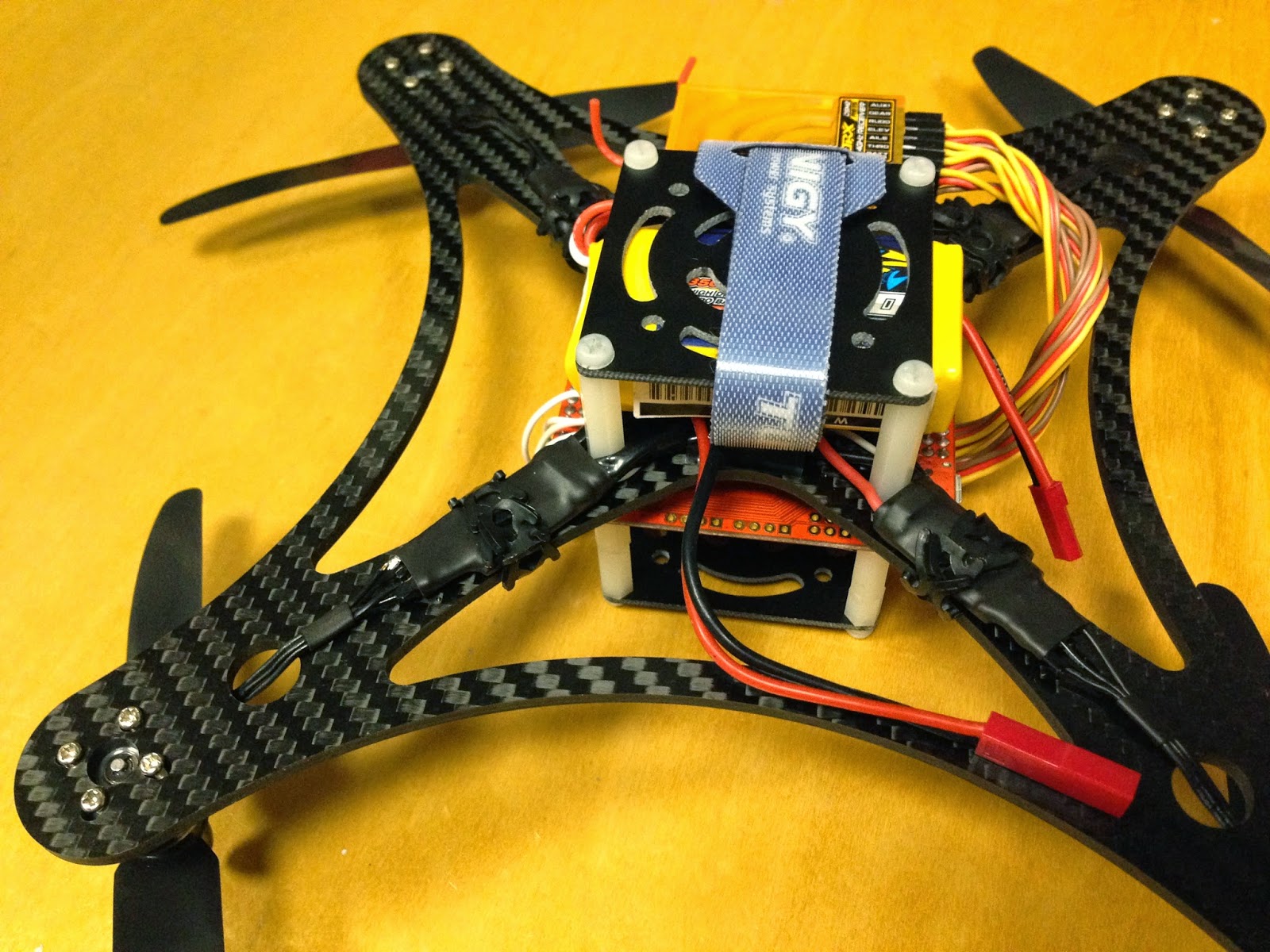
A shelf is added to the underside to act both as a battery tray and as a landing leg.  This will protect the vehicle while it is on contact with the ground. Additionally, the receiver was attached to the underside of the frame (at the front) using double-sided tape. 

We are just about there.  The electronics are all set up.  We just need to add the propellers and a battery.


For now I opted to use a 2S 850mAh 20C/30C battery.  Not trying to break any endurance records or performance records yet but just want to get this baby airborne.  This battery is small compact and has enough juice to spin these props.  Later, however, I will use a 2S 2,200mAh 20C/30C battery.  Finally I added the props.  I used Gemfan 5x3 props (2-bladed).  I also have a set of 4x2.5 props that I will test on the quad.  DO NOT USE 6-inch props!  Even though these will fit on the frame, they will cause the motors to draw too much current and you are likely to burn them out (and the ESCs) as a result.

All ready to go and this little guy tips the scales with an AUW of 262g.  The battery contributes about 50g to this so, without battery, this quad weighs 212g.  It's slightly higher than the 200g I was aiming for, but we're close and this quad has really high end components in its drive system.  Should be extremely agile at this weight - especially with 5-inch props.  Also, if acro and stability modes are all you are after, then there are more lightweight FCs available that would work just fine.  The 2,200mAh battery which I got for this quad weighs in at 134g.  With this battery, the quad weighs in at 346g which is a little heavier than the 300g AUW that I wait aiming for.  If necessary, we could always use a 1,600mAh which weighs in at 85g for an AUW of 297g.  The difference in flight times between the two is about 2 minutes.  Also, I have not yet added the GPS components which will likely add a few grams (about 5g) to the AUW.

This quad looks terrific and weighs nothing.  It easily fits in a backpack or in the palm of one's hand.
And just like that, we're done.  Meet my new baby.  A clean and neat minimalistic build.  Very pleased with the way this looks.  Time to go flying.

Wednesday, April 2, 2014

Flashing HobbyKing 20A ESC with SimonK Firmware

Standard ESCs are designed for cars and aircraft for which it is undesirable for the speed of the motors to change rapidly.  As such, the firmware running on the ESC accounts for this by ramping motor speeds up or down smoothly regardless of how rapid the change in inputs from the transmitter.  It achieves this by averaging the input signal with the n previous input signals before acting upon it; such filtering necessarily introduces latency in the response of the vehicle.  This latency can, under certain conditions, cause the control system to become unstable.  For the case of a multicopter, we'd like the change in rotor speeds (and thus thrust) to be as fast as possible which will improve the responsiveness of the vehicle. 

Additionally, the standard firmware incorporates other functions which are useful for fixed wing aircraft and cars but could very well be detrimental to multicopters (like a low voltage cutoff - designed to protect your LiPo battery from damage - clearly we don't want the multicopter's motors to shut off mid-flight.)

In a process known as RapidESC, the standard ESC is converted, at no cost, into a high performance, highly responsive ESC suitable for multirotor applications.  Specifically,  we will use open source firmware designed for this process by the legendary Simon Kirby who is well-known throughout the RC multirotor community simply as SimonK.  In the case of the SimonK firmware, the ESC is reprogrammed to run at 400Hz rather than its original speed of 8Hz.  It does, however, continue to average the current input signal with the last n values (which will eliminate spikes in the input), but because the ESC is sampling the input signal 400 times a second instead of 8 times a second, any change in the throttle input will result in an almost immediate change in the RPMs and thus the thrust of the motors.  The video below demonstrates the difference in responsiveness of the control system between an ESC running the standard firmware versus one running SimonK.


So, in short, the idea here is that we'd like to replace the existing firmware on the ESC with the SimonK firmware using a process called "flashing".  It should be noted that this firmware is, in many cases, both brand-specific and model-specific so be sure to select the correct one.  Here is a database containing containing flashing information for various ESC's including which firmware version to use for a particular ESC.  Before beginning it is necessary to identify the RapidESC firmware version that is suitable for the particular ESC being flashed.

Here's what I used...

Hardware

  1. HobbyKing Blue Series 20A ESC
  2. USBasp Programming Device for ATMEL Processors
  3. ATMEL Atmega Socket Firmware Flashing Tool
  4. Exacto Knife 
Note that (2) and (3) are made specifically for ATMEL processors.  In order to flash ESCs that use a different processor (like Silabs) will require a different (but similar) programming tool and socket connector.

Software

  1. KKmulticopter Flash Tool
 This software was, in fact, developed to flash the KK2 flight controller with the latest firmware.  It, however, also allows one to quickly and simply flash one's ESC with the latest version of SimonK firmware which is a .hex file and which can be downloaded automatically from an online repository.  Additionally, this software tool will run on Windows, Mac or Linux (although Windows might first require the installation of a driver for the USB programming device).

Preparing the ESC for flashing

Before the ESC can be flashed, we need to to be able to access the ATMEL processor on the ESC so that an electrical connection can be made.  For this purpose, the shrink wrap covering must be removed.  Rather than removing the entire shrink wrap from the ESC and then having to re-wrap the ESC afterwards it is easier to simply cut an access window/flap.  Use the Exacto knife to cut the shrink wrap around the ATMEL processor, as shown in the picture, on three sides to create a flap that can be folded back.  This now provides direct access to the ATMEL's electrical terminals for the socket tool.

NOTE:  There are two ways to get the correct orientation of the ATMEL processor (which is square in shape).  The first way is to look at the writing on the ATMEL.  If the writing is correctly oriented, then so is the chip.  The second way is to look for the dot on the ATMEL (ie a  small round impression on the ATMEL's plastic casing).  This indicates the top left corner and the chip should be oriented accordingly. 


The socket tool generally has a red dot on one of the corners and the socket tool should be connected to the ATMEL so that the red dot is in the TOP LEFT CORNER - ie the same corner of the ATMEL that contains the circular dot - so we match the dot on the socket tool with the dot on the ATMEL.  If the socket tool does not contain a dot (or if it has since been erased) then look at the pin configuration on the socket tool and you will notice that 4 of the 6 electrical connections are concentrated near one of the corners.  This concentration of pins connects to the LOWER RIGHT HAND corner of the AMTEL chip.

Flashing the ESC with SimonK firmware in 5 simple steps (on my Mac)

  1. Download and install the KKmulticopter flash software (just use the latest stable version).
  2. Plug the USBasp programmer into the USB port and connect the socket tool to the programmer.
  3. Launch the KKmulticopter software set the following:
    1. For the programmer, select "Any usbasp clone with correct VID/PID".
    2. For the controller, select "atmega 8 based brushless ESC + enable Bootloader (8kb flash)".  NOTE:  Make sure to select the "enable bootloader" option.
    3. For the firmware (which will be downloaded from an online repository) select "BS N-FET V2014-03-06 by Simon Kirby" or whatever the most recent update is.  If you are unsure of which version of the firmware to use then take a look at this list.
  4. Connect the socket tool to the ATMEL IN THE CORRECT ORIENTATION and hold it in place with one hand.  The pins in the tool are spring-loaded so it is easy to keep the ATMEL connected by applying a bit of downward pressure on the socket tool.
  5. With the other hand, click "Flash Firmware".  Whole process takes about 10 seconds.  You are done when you see "Flashing of firmware was successful".
DO NOT DISCONNECT THE FLASHING TOOL TOO SOON OR YOU RUN THE RISK OF PERMANENTLY DAMAGING YOUR ESC.  If you happen to disconnect or are otherwise confronted with red writing (an error) then just repeat steps 4 and 5.

Now close the flap of shrink wrap so that it covers the ATMEL again and add a small piece of tape to keep it in place and you're done.  

Voila.

Tuesday, March 11, 2014

Building My First Tricopter

Background

After having experimented with quads of varying sizes, I decided it was time to get my teeth stuck into some tricopter building.  Seeing that I would like to use the platform for aerial photography and for experimentation, I was looking for a frame that allowed me both the opportunity of carrying a meaningful payload while enduring as long as possible (with the goal being to keep it under 1,000g AUW while being able to hover for 15+ mins).

After considering a few different options, I decided on the new Turnigy Talon tricopter frame. 
The arms and hubs are made completely of carbon fiber with the mounting blocks for the arms as the motors made from machined aluminum.  Additionally, the arms are made from standard carbon fiber tubes and so can be easily replaced in the case of breakage (arms and propellers tend to be the most commonly broken frame parts on multicopters) .  Once assembled, the frame should weigh in at 350g (accoridng to its instructions) and serves as a good comparison to my DJI 450 quad frame in terms of its overall size, its payload capacity and the space available for mounting equipment.  One salient different is that this tricopter frame has folding arms which allow the frame to be flown three different configurations (including a T-shape) and configured in a fourth for compact storage.  In it's storage configuration it is much smaller than the DJI 450, so much so that it can be easily carried in a small backpack.  Another major difference between a tricopter and quadcopter is that the tricopter requires thrust vectoring of the rear motor/propeller combination in order to control yaw.  For this purpose, a servo is required and a digital servo using metal gears is the preferred way to go.  An ideal servo will have very fast response times, can take a fair amount of abuse and has good centering ability while the amount of torque it can handle is slightly less important. 

Frame Assembly

Assembly was a little tedious as the small parts are not well-suited to my fat fingers.  Additionally, the assembly instructions (which amounted to little more than a breakaway CAD drawing) were basically non-existent.  Would definitely not recommend this build for the beginner.

Steps:
  1. Assemble the arm mounts.


  2. Prepare the hub plates with the appropriate spacers and attachments.


  3. Mount the arms to the hub ensuring that the arms are able to fold properly.


  4. Prepare and attach the motor mounts to the ends of arm.


  5. Voila.  The foldable tricopter frame is compete.  The bare frame tips the scales at 352g.


Motors and Propeller Sizing

The selection of a motor and propeller for a tricopter is a fairly easy task - much more so than for a quad copter because there is almost no limitation in the size of the propeller one can choose.  While a 450 quadcopter frame can accommodate up to 12-inch propellers (although this even is slightly large due to the proximity of the tips), a similarly sized (and weighted) tricopter frame can accommodate up to 24-inch props (HUGE for a frame of this weight).  In this case we will go with 10 x 4.5 props for now.
     

Friday, January 24, 2014

Office Bot

I decided to build an autonomous bot to rove around my office.  The idea is to use this as a platform to develop and test new ideas for autonomous systems.  These systems will eventually be installed in our Aerobot.  This includes the ability to communicate with the internet using a wireless network.
 
After researching various platforms, I decided upon the Magician chassis at just $14.95 from Sparkfun and it includes two DC motors and gearboxes.  I will be using an Arduino Uno as the controller and this chassis is an appropriate size and provides and good amount of space with its two-shelf design.  This will accommodate the Arduino, a motor shield, battery and a small breadboard for prototyping as well as Sonar, WiFi and PIR sensors.

Assembling the chassis was a little bit tedious (especially for those of us with fat fingers) as there are numerous screws and holes to align.  That said, I am happy with the finished product.  It is sturdy and has ample room to mount sensors and controllers.  Moreover, its design allows one to readily attach additional shelves.  The two wheels plus caster design with a built-in 48:1 gearbox will enable it to roam smoothly along the carpeted floors of my office at a good pace and will also allow for maneuvering in tight spaces.   The Magician chassis also comes with a battery holder (4 x AA batteries) which provides 6V (which will power the Arduino Uno controller).  This was mounted on the lower shelf where it is tucked away out of sight (this will likely make the batteries a little tedious to change in the future as it will require disassembling the shelves).

Additional posts are provided with the chassis kit which are used to mount the controller board - though mounting the Arduino Uno to the shelf required a little jockeying around with the post, but such is the beauty of the shelf design; it provides tremendous flexibility.

So What's The Goal?

 The goal of this project is to build a robot the can autonomously roam my office.  While this goal is a rather vague and open-ended one (due to the fact that one can always add additional "intelligence" to the vehicle) suffice it to say that Phase 1 of this project should seek to achieve the following:

  1. COMMS:  Establish wireless communication ("comms") between the bot and a "ground station" computer.  Initially, an PC in my office will serve as the ground station.  The PC will thus be able to send instructions to the bot. 
  2. GUIDANCE:  Create a user interface for sending guidance instructions to the bot there by instructing it where to go.  While a general framework will be set up for this, for now only the the commands "forward" and "stop" will be implemented in Phase 1 (it is important with any project always to set up your "STOP/OFF" button first!)
  3. AUTONOMOUS CONTROL:  Using a combination of sensors and intelligence algorithms, the bot must be able to navigate the office while avoiding obstacles.  
So the idea is that if one commands "forward" on the PC, the bot should drive "forward" but should stop and turn in order to avoid obstacles (mostly cubicle walls for now).

Thursday, January 16, 2014

Controlling Arduino with iPhone using OSC

The iPhone's touch screen allows it to be used as a handy remote control user interface for all sorts of things.  For this project, I used my iPhone to control different electrical components.  The first goal was to use a button on the iPhone to turn an LED on and off and the second goal was to use a fader (potentiometer) control on the iPhone to control the speed of an electric motor (fan).

I used a technology called Open Sound Control (OSC) which is used in the music business to control various audio components (using MIDI).  Without getting into the benefits of OSC in too much detail, suffice it to say that this allows us to very quickly create different custom user interfaces for the purpose of controlling all sorts of things.  Think of the big sound boards with its sliders, buttons, toggles, faders, etc. that one finds in a recording studio - the ones that the sound engineers use.  This is what OSC gives you on your smart phone or tablet (which makes it portable).  It is used often by DJs at clubs that want to use their own, customized, familiar controls to control the music they are playing.  Connectivity is handled through WiFi.

TouchOSC


Of the various OSC apps available for iOS, I decided to go with TouchOSC based on the various reviews that I read.  In order to get OSC to work, a host machine must be set up to receive the OSC commands.  This is achieved by connecting both the iPhone and the host machine to the same WiFi network (yes, ad-hoc mode will work if you don't have a wireless router set up).  The host machine runs an event handler that catches the OSC commands and handles it accordingly by translating it into an instruction for the Arduino.  For the purpose of this project, the Arduino is connected directly to the host computer via USB cable and the serial port is used by the host computer to command the Arduino.  For a completely wireless setup, the Arduino can be linked to the host computer by WiFi, bluetooth or radio link depending on the application.  

There is a a downloadable layout editor provided for TouchOSC which allows one to quickly and easily produce a custom UI on your desktop computer and to sync with TouchOSC in order to upload the layout to the iPhone.

Host Computer


The Processing language was used for the purpose of coding the event handler for the host computer.  Processing is commonly used for interacting with Arduino as the two play very well together.  In fact, the Arduino IDE was derived from the Processing IDE which is why they look so similar.  While the Arduino language has its origins in C/C++, the Processing language comes from JAVA.  This means that the same sketch (the term used for a Processing and Arduino program) can be used on MacOS, Windows, Unix/Linux and can readily be compiled for use on Android OS.  Additionally, Processing is supported by a huge open source community and, consequently, there are libraries and sketches already available for many different things - including OSC handling.

Controlling an LED


Circuitry

For the purpose on this demonstration,  a simple circuit was set up containing an LED plus a resistor connected to the cathode (-ve terminal) of the LED.  The other end of the resistor was connected to ground on the Arduino while the LED's anode (+ve terminal) was connected to digital pin 9 on the Arduino.  By writing a HIGH or LOW value to pin 9, the LED can be turned on and off respectively.

Arduino Sketch

The Arduino sketch is very simple and pretty much just contains an event handler which monitors the serial port for any data (in this case only 1 byte of data is being communicated each time).  In this case, the data being sent is simply a "1" or a "0" from which the Arduino determines whether to send a HIGH or LOW voltage to pin 9.  A copy of the sketch can be download from here.


Processing Sketch

The Processing sketch is slightly more involved than the Arduino sketch (although only slightly).  Using Processing, the host computer must also run an event handler in order to receive commands from TouchOSC on the iPhone.  The handler catches the incoming message from TouchOSC, parses the message in order to determine which control sent the message and the corresponding value.  

TouchOSC

In this case, we just needed a simple on/off toggle switch.  A custom layout was created containing a toggle switch (which I named 'toggle1') and was set to send the values of '0' or '1' depending on the state of the toggle.  IMPORTANT:  Under Settings-->Connections-->OSC, the host name must be set to the IP address of the host computer.  The host computer should be configured with a static IP address to ensure that it won't somehow change unexpectedly.

So, in this case a typical message sent from TouchOSC will look something like "1/toggle1" followed by a value (in this case a 0 or 1).  By parsing this message, the processing code determines which control was changed (in this case it is only toggle1).  For a more general set up, the Processing sketch should be abstracted so that it can handle different types of controls.  In general (although not used in this case), the Processing sketch will send a different range of values to those that the Arduino is expecting so there is usually some mapping that is handled by Processing.  For example, you could have set a knob on TouchOSC to send the value of 0 to 180 (which indicates how many degrees the knob has been turned).  This range of 0 to 180 degrees might need to be mapped to a value of, say, 0 to 100 before sending it to the Arduino. 


Controlling an Electric Motor/Fan


Circuitry

I decided to build a test rig in order to test various motor/propeller combinations in order to determine the thrust output and the efficiency of different combinations while spinning at different RPMs.  The test rig is made from wood onto which an electric motor was mounted (NOTE:  it is a good idea to attach the propeller only AFTER one is sure that everything is working as expected so that nobody can get hurt).  I attached an ESC (30A) to the motor to which I attached a big 4S (14.8V) battery to power the motor and then attached the control wire's ground and signal wires to the Arduino's ground and digital pin 9 respectively.  Do NOT connect the power wire to the Arduino.

WARNING: These ESCs contain a battery elimination circuit (BEC) for the purpose of providing power from the flight battery to the receiver and thereby eliminating the need for a separate receiver battery.  Consequently, the red power line of the ESC's control wire is hot (it carries 5V at up to 3 amps).  It could be used to power the Arduino, but the Arduino is already getting its power from the host computer's USB port.  

IF YOU CONNECT YOUR ESC'S POWER LINE TO THE ARDUINO'S 5V PIN, YOU STAND A GOOD CHANCE OF BLOWING BOTH YOUR ARDUINO AND THE USB PORT ON YOUR COMPUTER.


Arduino Sketch

For the purpose of controlling the ESC, the Arduino's servo library was used.  A couple of things to bear in mind is that servos are controlled by sending a value of 0 to 255 along the control wire.  In order to achieve this, the signal wire on the servo must be connected to a pin on the Arduino that is capable of pulse-width modulation (PWM).  In the case of the Arduino nano that was used here, port 9 will work just fine.  Just to complicate matters a little, we are obviously not controlling a servo, but rather an ESC.  The difference is that, in the case of an ESC, sending a value of 0 to the ESC does NOT usually correspond to the zero-throttle setting of the ESC (it is actually a negative throttle setting).  

Why is this important.  Well, for one thing, when you first power up the ESC's they start up in safe mode in so that the motors do not suddenly run unexpectedly.  Upon powering up the ESC, it proceeds with a chime and then continues to beep to indicate that it is in safe mode.  In order to arm the ESC, the throttle must be reduced to zero at which time the beeping stops.  In order to find this value, the Arduino was powered up and then different values were sent via the serial port monitor to the ESC and it was discovered the a value of 50 armed the ESC - so a signal value of 50 corresponds to zero throttle (this is different for different ESCs) and 255 is full throttle.  Note that this relationship between signal input and motor speed is not a linear one.


Processing Sketch

The Processing sketch was modified slightly.  On the one hand, instead of the control being a toggle switch, it is now a potentiometer (called a fader).  This fader can be adjusted from 0 to 180 degrees (or whatever mapping one prefers).  In this case, the value received by the sketch must first be mapped to a range of values that the ESC expects to receive.  it should be noted that TouchOSC will send only integer values to the host computer (no fractional values are used).  If a higher resolution is desired for the fader knob, then the range of values from the fader could be set to be 0 to 1800.

The value of the fader (0 to 180) is then mapped to the range of output signals which is 50 to 255 (as mentioned above).


TouchOSC

Once again a custom UI was designed using layout editor.  In this case, it consisted of simply a fader knob which was set to output values in the range of 0 to 180.  Custom layout was uploaded to TouchOSC on the iPhone.


Thursday, January 9, 2014

An F550 Hexcopter for Aerial Photography

Since I really liked the agility of my quadcopter, I wanted to keep it that way and, so, for a stable aerial photography platform, I opted for a hexcopter.  I got a great deal on a DJI Flame Wheel F550 combo package which included DJI's NAZA-M v2 flight controller with GPS (which is just killa'), a Zenmuse H3-2D gimbal for a GoPro camera (which I already have) and DJI's landing gear so that the gimbal and camera can be mounted underneath the copter.  All of this should make for a very stable aerial platform.

NAZA-M V2 Flight Controller


NAZA-M V2 Flight Controller
The assembly followed much the same procedure as that for the quadcopter project although the setup of the NAZA took a little while as I wanted to familiarize myself with the assistant software and all the features of the NAZA controller (it will supposedly fly OTB but I wanted to dig into its features).  Also,  since I have an older Spektrum DX7 transmitter, I needed to perform some custom programming in order to allow me to activate the various functions on the NAZA controller (like the Return-To-Home fail-safe option).

The first thing I tested was the GPS-lock mode (commonly referred to as Loiter Mode).  In this mode, the flight controller should not only hold the attitude of the vehicle, but should also keep it at a given location in space - this includes altitude.  In this video, the ability of the F550 to return to its prescribed location and also its ability to takeoff and then land on the same spot is tested.  Before mounting and possibly losing expensive camera equipment, it was necessary to test the ability for the F550 to be easily and steadily controlled and recovered.  As can be seen in the video, the NAZA FC kept the F550 on the spot.  With a good lock on several satellites, the NAZA performs extremely well in this role.  The controller does have a sluggish feel to it.  It flies very well and with much stability and it feels like it.

It is important to realize that these vehicles are unstable by design and would crash very quickly without a controller, (although not so much that it can't be flown manually by a pilot).  Consequently, any computer-augmented control is really a fly-by-wire (actually wireless) design.  Different flight characteristics can be build into the flight controller.  In the case of the NAZA-M, this controller is designed to be smooth and stable and flying the quad with it feels that way.  Switching the controller to manual really gives the F550 a much more aggressive nature.


In a rush to get some aerial photography (AP) going, I decided to mount my GoPro directly to the F550 using one of the standard mounts that came with the camera plus some double-sided tape.  Video was a little choppy, but great to see.

Zenmuse H3-2D Gimbal


Zenmuse H3-2D Gimbal by DJI
Having satisfied myself that the flight controller was working properly, I then proceeded to mount the Zenmuse H3-2D gimbal on which to mount the GoPro.  This Zenmuse is especially designed for the GoPro camera.  It holds it, stabilizes it and allows one to remotely control the camera's shooting as well as controlling the pitch on the camera.  Since the Zenmuse it 2D, it stabilizes in pitch and roll only.  Additionally, as mentioned, the camera can be remotely tilted using the transmitter.  Yaw control of the camera is performed by yawing the vehicle.  When the battery is connected to the vehicle and the gimbal powered, the GoPro will recharge itself.  Additionally, the gimbal provides a video out line which can be used to send the video signal to a video transmitter for real-time viewing at the ground station.

Unfortunately, the Zenmuse does not attach readily to the frame of the F550 (which I found very strange since both are made by DJI - it does, however, attach readily to the frame of the F450).  For now, I simply attached the mounting plate of the gimbal to the underneath of the F550's hub using cable ties.  This worked pretty well except that (because of the wide angle lens of the GoPro) the langing gear appears in the camera's view.  Soon I will 3D print a custom mounting plate for the gimbal that will take care of this.  For now, I will just have to live with the sight of the landing gear.  Initial testing of the Zenmuse gimbal shows that it works very well in stabilizing the camera.


The real test, of course, comes from flying the copter.  Took the F550 up over UCLA for a scenic flight.  Zenmuse results in a beautiful, stable picture.


Back at the park for another go round and starting to put the F550 through its paces.  Flying it more and more aggressively as I develop a feel for its performance.


Return-To-Home (RTH) Failsafe Setting

Before adding too much expensive equipment to the vehicle, I wanted to ensure that the the controller's failsafe feature was enabled, active and working correctly.  The idea here is that in case of an emergency, I can flip a switch on the radio and the RTH function will be activated.  When activated, the vehicle will climb to 20 meters (this can be adjusted) if it is below that altitude, return to the location from where it took off and will land itself gently (assuming sufficient power remains in the battery).  If, when RTF is activated, the vehicle is above 20m in altitude, then it will retain that altitude, fly itself home and land.  In the event that the vehicle flies out of range of the radio and the signal drops, the NAZA will automatically enter RTH mode after 3 seconds of signal loss.  The video below shows a test of the RTH feature.


First Person View (FPV)

The idea behind FPV is that by attaching a video transmitter to the hexcopter, we can turn the GoPro video with a live stream that can be viewed in real-time at the ground station using either a video monitor of a pair of video goggles.  Using this video image, the pilot can control the vehicle well beyond the visible range by, in effect, putting the pilot in the "cockpit" of the vehicle and allowing him to steer from that point-of-view.

MORE SOON...