I decided to build an autonomous bot to rove around my office. The idea is to use this as a platform to develop and test new ideas for autonomous systems. These systems will eventually be installed in our Aerobot. This includes the ability to communicate with the internet using a wireless network.
After researching various platforms, I decided upon the Magician chassis at just $14.95 from Sparkfun and it includes two DC motors and gearboxes. I will be using an Arduino Uno as the controller and this chassis is an appropriate size and provides and good amount of space with its two-shelf design. This will accommodate the Arduino, a motor shield, battery and a small breadboard for prototyping as well as Sonar, WiFi and PIR sensors.
Assembling the chassis was a little bit tedious (especially for those of us with fat fingers) as there are numerous screws and holes to align. That said, I am happy with the finished product. It is sturdy and has ample room to mount sensors and controllers. Moreover, its design allows one to readily attach additional shelves. The two wheels plus caster design with a built-in 48:1 gearbox will enable it to roam smoothly along the carpeted floors of my office at a good pace and will also allow for maneuvering in tight spaces. The Magician chassis also comes with a battery holder (4 x AA batteries) which provides 6V (which will power the Arduino Uno controller). This was mounted on the lower shelf where it is tucked away out of sight (this will likely make the batteries a little tedious to change in the future as it will require disassembling the shelves).
Additional posts are provided with the chassis kit which are used to mount the controller board - though mounting the Arduino Uno to the shelf required a little jockeying around with the post, but such is the beauty of the shelf design; it provides tremendous flexibility.
So What's The Goal?
The goal of this project is to build a robot the can autonomously roam my office. While this goal is a rather vague and open-ended one (due to the fact that one can always add additional "intelligence" to the vehicle) suffice it to say that Phase 1 of this project should seek to achieve the following:
COMMS: Establish wireless communication ("comms") between the bot and a "ground station" computer. Initially, an PC in my office will serve as the ground station. The PC will thus be able to send instructions to the bot.
GUIDANCE: Create a user interface for sending guidance instructions to the bot there by instructing it where to go. While a general framework will be set up for this, for now only the the commands "forward" and "stop" will be implemented in Phase 1 (it is important with any project always to set up your "STOP/OFF" button first!)
AUTONOMOUS CONTROL: Using a combination of sensors and intelligence algorithms, the bot must be able to navigate the office while avoiding obstacles.
So the idea is that if one commands "forward" on the PC, the bot should drive "forward" but should stop and turn in order to avoid obstacles (mostly cubicle walls for now).
The iPhone's touch screen allows it to be used as a handy remote control user interface for all sorts of things. For this project, I used my iPhone to control different electrical components. The first goal was to use a button on the iPhone to turn an LED on and off and the second goal was to use a fader (potentiometer) control on the iPhone to control the speed of an electric motor (fan).
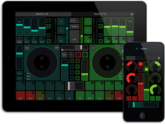
I used a technology called Open Sound Control (OSC) which is used in the music business to control various audio components (using MIDI). Without getting into the benefits of OSC in too much detail, suffice it to say that this allows us to very quickly create different custom user interfaces for the purpose of controlling all sorts of things. Think of the big sound boards with its sliders, buttons, toggles, faders, etc. that one finds in a recording studio - the ones that the sound engineers use. This is what OSC gives you on your smart phone or tablet (which makes it portable). It is used often by DJs at clubs that want to use their own, customized, familiar controls to control the music they are playing. Connectivity is handled through WiFi.
TouchOSC
Of the various OSC apps available for iOS, I decided to go with TouchOSC based on the various reviews that I read. In order to get OSC to work, a host machine must be set up to receive the OSC commands. This is achieved by connecting both the iPhone and the host machine to the same WiFi network (yes, ad-hoc mode will work if you don't have a wireless router set up). The host machine runs an event handler that catches the OSC commands and handles it accordingly by translating it into an instruction for the Arduino. For the purpose of this project, the Arduino is connected directly to the host computer via USB cable and the serial port is used by the host computer to command the Arduino. For a completely wireless setup, the Arduino can be linked to the host computer by WiFi, bluetooth or radio link depending on the application.
There is a a downloadable layout editor provided for TouchOSC which allows one to quickly and easily produce a custom UI on your desktop computer and to sync with TouchOSC in order to upload the layout to the iPhone.
Host Computer
The Processing language was used for the purpose of coding the event handler for the host computer. Processing is commonly used for interacting with Arduino as the two play very well together. In fact, the Arduino IDE was derived from the Processing IDE which is why they look so similar. While the Arduino language has its origins in C/C++, the Processing language comes from JAVA. This means that the same sketch (the term used for a Processing and Arduino program) can be used on MacOS, Windows, Unix/Linux and can readily be compiled for use on Android OS. Additionally, Processing is supported by a huge open source community and, consequently, there are libraries and sketches already available for many different things - including OSC handling.
Controlling an LED
Circuitry
For the purpose on this demonstration, a simple circuit was set up containing an LED plus a resistor connected to the cathode (-ve terminal) of the LED. The other end of the resistor was connected to ground on the Arduino while the LED's anode (+ve terminal) was connected to digital pin 9 on the Arduino. By writing a HIGH or LOW value to pin 9, the LED can be turned on and off respectively.
Arduino Sketch
The Arduino sketch is very simple and pretty much just contains an event handler which monitors the serial port for any data (in this case only 1 byte of data is being communicated each time). In this case, the data being sent is simply a "1" or a "0" from which the Arduino determines whether to send a HIGH or LOW voltage to pin 9. A copy of the sketch can be download from here.
Processing Sketch
The Processing sketch is slightly more involved than the Arduino sketch (although only slightly). Using Processing, the host computer must also run an event handler in order to receive commands from TouchOSC on the iPhone. The handler catches the incoming message from TouchOSC, parses the message in order to determine which control sent the message and the corresponding value.
TouchOSC
In this case, we just needed a simple on/off toggle switch. A custom layout was created containing a toggle switch (which I named 'toggle1') and was set to send the values of '0' or '1' depending on the state of the toggle. IMPORTANT: Under Settings-->Connections-->OSC, the host name must be set to the IP address of the host computer. The host computer should be configured with a static IP address to ensure that it won't somehow change unexpectedly.
So, in this case a typical message sent from TouchOSC will look something like "1/toggle1" followed by a value (in this case a 0 or 1). By parsing this message, the processing code determines which control was changed (in this case it is only toggle1). For a more general set up, the Processing sketch should be abstracted so that it can handle different types of controls. In general (although not used in this case), the Processing sketch will send a different range of values to those that the Arduino is expecting so there is usually some mapping that is handled by Processing. For example, you could have set a knob on TouchOSC to send the value of 0 to 180 (which indicates how many degrees the knob has been turned). This range of 0 to 180 degrees might need to be mapped to a value of, say, 0 to 100 before sending it to the Arduino.
Controlling an Electric Motor/Fan
Circuitry
I decided to build a test rig in order to test various motor/propeller combinations in order to determine the thrust output and the efficiency of different combinations while spinning at different RPMs. The test rig is made from wood onto which an electric motor was mounted (NOTE: it is a good idea to attach the propeller only AFTER one is sure that everything is working as expected so that nobody can get hurt). I attached an ESC (30A) to the motor to which I attached a big 4S (14.8V) battery to power the motor and then attached the control wire's ground and signal wires to the Arduino's ground and digital pin 9 respectively. Do NOT connect the power wire to the Arduino.
WARNING: These ESCs contain a battery elimination circuit (BEC) for the purpose of providing power from the flight battery to the receiver and thereby eliminating the need for a separate receiver battery. Consequently, the red power line of the ESC's control wire is hot (it carries 5V at up to 3 amps). It could be used to power the Arduino, but the Arduino is already getting its power from the host computer's USB port.
IF YOU CONNECT YOUR ESC'S POWER LINE TO THE ARDUINO'S 5V PIN, YOU STAND A GOOD CHANCE OF BLOWING BOTH YOUR ARDUINO AND THE USB PORT ON YOUR COMPUTER.
Arduino Sketch
For the purpose of controlling the ESC, the Arduino's servo library was used. A couple of things to bear in mind is that servos are controlled by sending a value of 0 to 255 along the control wire. In order to achieve this, the signal wire on the servo must be connected to a pin on the Arduino that is capable of pulse-width modulation (PWM). In the case of the Arduino nano that was used here, port 9 will work just fine. Just to complicate matters a little, we are obviously not controlling a servo, but rather an ESC. The difference is that, in the case of an ESC, sending a value of 0 to the ESC does NOT usually correspond to the zero-throttle setting of the ESC (it is actually a negative throttle setting).
Why is this important. Well, for one thing, when you first power up the ESC's they start up in safe mode in so that the motors do not suddenly run unexpectedly. Upon powering up the ESC, it proceeds with a chime and then continues to beep to indicate that it is in safe mode. In order to arm the ESC, the throttle must be reduced to zero at which time the beeping stops. In order to find this value, the Arduino was powered up and then different values were sent via the serial port monitor to the ESC and it was discovered the a value of 50 armed the ESC - so a signal value of 50 corresponds to zero throttle (this is different for different ESCs) and 255 is full throttle. Note that this relationship between signal input and motor speed is not a linear one.
Processing Sketch
The Processing sketch was modified slightly. On the one hand, instead of the control being a toggle switch, it is now a potentiometer (called a fader). This fader can be adjusted from 0 to 180 degrees (or whatever mapping one prefers). In this case, the value received by the sketch must first be mapped to a range of values that the ESC expects to receive. it should be noted that TouchOSC will send only integer values to the host computer (no fractional values are used). If a higher resolution is desired for the fader knob, then the range of values from the fader could be set to be 0 to 1800.
The value of the fader (0 to 180) is then mapped to the range of output signals which is 50 to 255 (as mentioned above).
TouchOSC
Once again a custom UI was designed using layout editor. In this case, it consisted of simply a fader knob which was set to output values in the range of 0 to 180. Custom layout was uploaded to TouchOSC on the iPhone.
Since I really liked the agility of my quadcopter, I wanted to keep it that way and, so, for a stable aerial photography platform, I opted for a hexcopter. I got a great deal on a DJI Flame Wheel F550 combo package which included DJI's NAZA-M v2 flight controller with GPS (which is just killa'), a Zenmuse H3-2D gimbal for a GoPro camera (which I already have) and DJI's landing gear so that the gimbal and camera can be mounted underneath the copter. All of this should make for a very stable aerial platform.
NAZA-M V2 Flight Controller
NAZA-M V2 Flight Controller
The assembly followed much the same procedure as that for the quadcopter project although the setup of the NAZA took a little while as I wanted to familiarize myself with the assistant software and all the features of the NAZA controller (it will supposedly fly OTB but I wanted to dig into its features). Also, since I have an older Spektrum DX7 transmitter, I needed to perform some custom programming in order to allow me to activate the various functions on the NAZA controller (like the Return-To-Home fail-safe option).
The first thing I tested was the GPS-lock mode (commonly referred to as Loiter Mode). In this mode, the flight controller should not only hold the attitude of the vehicle, but should also keep it at a given location in space - this includes altitude. In this video, the ability of the F550 to return to its prescribed location and also its ability to takeoff and then land on the same spot is tested. Before mounting and possibly losing expensive camera equipment, it was necessary to test the ability for the F550 to be easily and steadily controlled and recovered. As can be seen in the video, the NAZA FC kept the F550 on the
spot. With a good lock on several satellites, the NAZA performs
extremely well in this role. The controller does have a sluggish feel to it. It flies very well and with much stability and it feels like it.
It is important to realize that these vehicles are unstable by design and would crash very quickly without a controller, (although not so much that it can't be flown manually by a pilot). Consequently, any computer-augmented control is really a fly-by-wire (actually wireless) design. Different flight characteristics can be build into the flight controller. In the case of the NAZA-M, this controller is designed to be smooth and stable and flying the quad with it feels that way. Switching the controller to manual really gives the F550 a much more aggressive nature.
In a rush to get some aerial photography (AP) going, I decided to mount my GoPro directly to the F550 using one of the standard mounts that came with the camera plus some double-sided tape. Video was a little choppy, but great to see.
Zenmuse H3-2D Gimbal
Zenmuse H3-2D Gimbal by DJI
Having satisfied myself that the flight controller was working properly, I then proceeded to mount the Zenmuse H3-2D gimbal on which to mount the GoPro. This Zenmuse is especially designed for the GoPro camera. It holds it, stabilizes it and allows one to remotely control the camera's shooting as well as controlling the pitch on the camera. Since the Zenmuse it 2D, it stabilizes in pitch and roll only. Additionally, as mentioned, the camera can be remotely tilted using the transmitter. Yaw control of the camera is performed by yawing the vehicle. When the battery is connected to the vehicle and the gimbal powered, the GoPro will recharge itself. Additionally, the gimbal provides a video out line which can be used to send the video signal to a video transmitter for real-time viewing at the ground station.
Unfortunately, the Zenmuse does not attach readily to the frame of the F550 (which I found very strange since both are made by DJI - it does, however, attach readily to the frame of the F450). For now, I simply attached the mounting plate of the gimbal to the underneath of the F550's hub using cable ties. This worked pretty well except that (because of the wide angle lens of the GoPro) the langing gear appears in the camera's view. Soon I will 3D print a custom mounting plate for the gimbal that will take care of this. For now, I will just have to live with the sight of the landing gear. Initial testing of the Zenmuse gimbal shows that it works very well in stabilizing the camera.
The real test, of course, comes from flying the copter. Took the F550 up over UCLA for a scenic flight. Zenmuse results in a beautiful, stable picture.
Back at the park for another go round and starting to put the F550 through
its paces. Flying it more and more aggressively as I develop a feel for its
performance.
Return-To-Home (RTH) Failsafe Setting
Before adding too much expensive equipment to the vehicle, I wanted to ensure that the the controller's failsafe feature was enabled, active and working correctly. The idea here is that in case of an emergency, I can flip a switch on the radio and the RTH function will be activated. When activated, the vehicle will climb to 20 meters (this can be adjusted) if it is below that altitude, return to the location from where it took off and will land itself gently (assuming sufficient power remains in the battery). If, when RTF is activated, the vehicle is above 20m in altitude, then it will retain that altitude, fly itself home and land. In the event that the vehicle flies out of range of the radio and the signal drops, the NAZA will automatically enter RTH mode after 3 seconds of signal loss. The video below shows a test of the RTH feature.
First Person View (FPV)
The idea behind FPV is that by attaching a video transmitter to the hexcopter, we can turn the GoPro video with a live stream that can be viewed in real-time at the ground station using either a video monitor of a pair of video goggles. Using this video image, the pilot can control the vehicle well beyond the visible range by, in effect, putting the pilot in the "cockpit" of the vehicle and allowing him to steer from that point-of-view.


 Assembling the chassis was a little bit tedious (especially for those of us with fat fingers) as there are numerous screws and holes to align. That said, I am happy with the finished product. It is sturdy and has ample room to mount sensors and controllers. Moreover, its design allows one to readily attach additional shelves. The two wheels plus caster design with a built-in 48:1 gearbox will enable it to roam smoothly along the carpeted floors of my office at a good pace and will also allow for maneuvering in tight spaces. The Magician chassis also comes with a battery holder (4 x AA batteries) which provides 6V (which will power the Arduino Uno controller). This was mounted on the lower shelf where it is tucked away out of sight (this will likely make the batteries a little tedious to change in the future as it will require disassembling the shelves).